Wellcome to Electrical Wiring CAD homepage
Eletrical Wiring CAD is a program aiming to facilitate the design of the electrical wiring in a house or flat
It is based on qcad community edition a very simple and fast CAD application written in C++ and utilizing the world renouned Qt toolkit for its graphics.
For the time being no real development has taken place but i intend to work hard on it during this summer so stay tuned.
What will Electrical Wiring CAD look like?
Actually i do not really know :-). What i can tell you for now is my vision for the basic functionality i intend to implement.
The basic idea is that you take a drawing of a floor plan in DXF (Data Exchange Format). This is convenient in two ways. First it is the only format fully supported in qcad. Secondly AutoCAD, the most popular CAD application, supports this format fully. That means it can convert DXF files to its native dwg format and vice versa. Furthermore DXF is well documented which helps in the development process.
After you have aquired the DXF file you open it in Electrical Wiring CAD (ewcad for short) and you design the electrical appliances like light bulbs, switches, wires, the fuse panel etc, using standard CAD entities. After that you will be able to attach electrical properties to these elements, probably through a menu. From then on ewcad should produce the summary electrical wiring drawing and produce the calculations to specify which protective elements are needed, the cross section of the wires and some additional data needed by health and safety regulations.
Here is a more graphical overview of what the basic work cycle will be like. Note that i use qcad for this demonstration which of course is very close to what the real thing will be like.
First import the drawing of a house floor.
Then go on and draw the electrical elements on the imported drawing
After you have put the electrical elements on the drawing you will be able to define their electrical properties. Using the provided data ewcad should produce all needed documents and drawings.
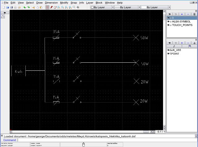
The following image is a sample output drawing of the summarized electrical circuit. Bare in mind that the values are off the top of my head so their correctness is seriously doudted.


